Printing the 6x12 Roll Film Holder by Edgar Kech
The 6x12 Format
This is a ‘6 on 120’ format, where the exposed frame is approximately 58mm x 116mm. This is about as large a format that will fit on a standard 5x4 camera back and still be a useful multiple of the 120 film length. The next size up is 6x17, which requires an expansion to the camera back, a dedicated 6x17 camera, or a larger format camera such as a 5x7 or 8x10. New 6x12 or multi-format roll film holders retail at several hundred dollars, so this printed version is something worth looking at if one wants to dabble in 6x12.
The Design
This roll fim holder has some similarities to the Horseman and DAYI designs, which is inevitable given the mounting requirements on 4x5 cameras and the necessary film path. It is a manual ‘red window’ film advance, using the even numbered frames from the 6x6 markings on the backing paper. The assembled unit consists of the base/camera mounting, the film holders/pressure plate, and a lightproof cover. The base includes the dark slide which is not intended to be fully withdrawn. I have fitted it to a cameras with a graflock back (MPP VII and the Intrepid 4x5 reducing back for theit 8x10) and to cameras using bungee cord retainers (Will Travel). It is unlikely to fit under a spring back due to the depth of the unit and impact on the focusing screen. This is NOT a Cambo slide-in replacement.
 The film path is a little unexpected unless you remember that the backing paper has to be visible through the ‘red window’ hole. The film
reel goes into the source chamber so that the backing paper leads out closest to the camera side. Once it has been drawn across the pressure surface,
it is fed onto the takeup spool from below while winding the backing paper black/film side in.
Keeping instructions with the back is probably a wise move.
The film path is a little unexpected unless you remember that the backing paper has to be visible through the ‘red window’ hole. The film
reel goes into the source chamber so that the backing paper leads out closest to the camera side. Once it has been drawn across the pressure surface,
it is fed onto the takeup spool from below while winding the backing paper black/film side in.
Keeping instructions with the back is probably a wise move.
The film holder fits onto the baseplate/darkslide assembly, and the cover fits over the top. The whole unit is held together by
two bolts with wing nuts or knobs. Connection to the camera can be by the usual graflock slides with the ground glass holder removed.
In the case of a Will Travel the bungee cord and a hook suffice.
Printing
Grab a copy of the details from the Thingiverse page - there is a lot of information there about materials and building which are not in the downloaded file set.
I used supports to the build plate for the film chamber cover, which was printed closed side down. This meant that the clean up was limited to the area either side of the bolt holes and not inside the film chambers. Look at the parts with a view to how your printer behaves, and choose the best orientation and supports accordingly.
There are three parts which are intended as a friction fit into dovetailed slots. These are the two removable pins that locate the film spools, and the sliding cover for the film frame number cover. Gentle sanding and frequent testing for fit are required to get these right. They should be tight enough to stay put, but loose enough to be moved easily. The spool locating pins should be able to be pushed out by gripping the spool and pushing sideways. They are held in place when the cover is on, but you do not want them so loose that they fall out.
I found I had to sand and shape the paddles that go into the winding knobs to get clearance to remove the spools. Do a few dry runs before gluing these parts together, and try different spools if you use film from different manufacturers.
Remember to install the velvet ribbon before gluing the two parts of the base plate together. I used a glue stick on the back of the ribbon to help fix any loose threads while fixing it in place. Be careful not to get glue on the front face. This is the same glue I use on the 3D printer bed, and should work. Only time will tell. It pays to have the darkslide in position while you do this, as it is best if the darkslide is never extracted and reinserted. Do smooth the darkslide edges to avoid damage to the light trap or wear on the plastic. I added a small grip to the end of the darkslide. If the light trap moves, the two components will have to be re-printed as separating the two halves would be difficult.
The strips cut from a drink can that are used to add friction to the film advance were set to curl under the spools after being inserted in the slots. The curve of the metal acts as a grip in the slot, and naturally follows the spools. I did not glue them in, since I don’t know if they will need to be replaced in time. Do smooth the edges and corners, as the metal is thin and sharp.
The design calls for M6 30mm bolts and knurled nuts. I used wing nuts, and as I could not find black bolts I roughened the heads and painted them. You could probably use 1/4-20 1-1/4 in. length bolts and wing nuts in the US if M6 items are hard to source. Either way, keep a spare set in your bag in the field. Without the bolt, there is a light leak.
I applied flat black paint to the inside of the film chamber and to any other areas likely to reflect light, but not on areas where the film or darkslide might cause friction. The paint not only serves to reduce reflections from the plastic, but also adds a little extra density for light proofing.
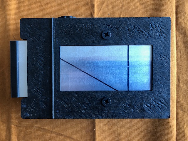 The darkslide was marked with lines showing the open and closed limits and a diagonal line drawn from opposite corners of the two limit lines.
This was done on both sides using a black Sharpie marker. The diagonal gives a visual warning of where the limit lines are so that the darkslide
is not withdrawn too far. This is similar to the markings on my Cambo roll-film back, so the two are consistent.
The darkslide was marked with lines showing the open and closed limits and a diagonal line drawn from opposite corners of the two limit lines.
This was done on both sides using a black Sharpie marker. The diagonal gives a visual warning of where the limit lines are so that the darkslide
is not withdrawn too far. This is similar to the markings on my Cambo roll-film back, so the two are consistent.
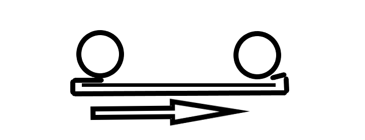
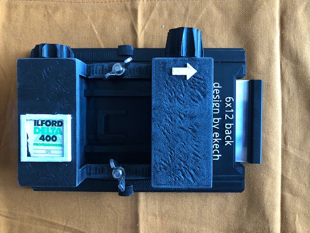
In addition to the darkslide grip mentioned above, I added a film box top holder (see Thingiverse again), and designed an arrow in OpenSCAD to remind me which way to wind the takeup spool.
In Use
 I usually advance the camera or film back to a new unexposed frame, so that is my starting point. Before making an exposure,
check that the shutter is closed (on view cameras the shutter is opened to focus on the ground glass screen). Set the shutter and aperture as required.
Cock the shutter, withdraw the darkslide to the limit mark (not all the way), and make the exposure.
I usually advance the camera or film back to a new unexposed frame, so that is my starting point. Before making an exposure,
check that the shutter is closed (on view cameras the shutter is opened to focus on the ground glass screen). Set the shutter and aperture as required.
Cock the shutter, withdraw the darkslide to the limit mark (not all the way), and make the exposure.
Then slide in the darkslide, and advance to the next even number in the frame number window. Close the window cover after use.
Provided the darkslide is fully seated, the back can be removed at any time. It is not possible to remove the film chamber and cover mid-roll without exposing part of the film.
The film path tends to straighten the normal film curl. If this is a problem when loading the film for processing, just leave the exposed roll tightly wound for a while to reset the curl.
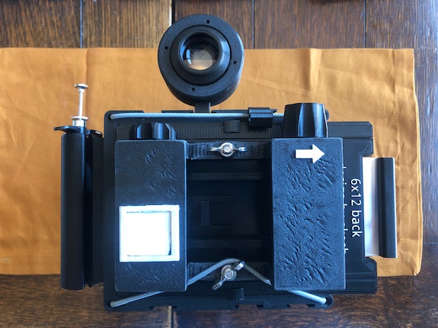
When used on a view camera, the framing can be done using a mask over the ground glass (Cut a sheet of black paper to fit over the ground glass, then mount just the base of the 6x12 holder and mark the aperture dimensions. Finally cut out the aperture.) or marked with a washable pen. It pays to use the base of the film holder as a template, as the mounting may not be exactly centred on the camera. When used with a direct vision camera such as the Will Travel, I use the finder designed by Morten Kolve for the Will Travel cameras with a custom mask that is proportionally smaller than the standard 4x5 opening. It does not allow for parallax, but it is good enough.
The exposed area on the negative is 55mm x 111mm. For comparison, a standard 4x5 holder gives an exposed area of 96mm x 121mm. So the 6x12 is 54% of the area of a 4x5 negative.
There is at least one remix on Thingiverse for a 6x9 aperture version. Smaller format roll-fim holders are more easily found, however, so a printed version is less attractive. It would probably be wise to be cautious about using infra-red sensitive film. The plastics used in 3D printers are not as infra-red resistant as metal.
Light Leaks
It looks like it pays to print the cover with extra walls and heavy infill. My first test showed a light leak where the film passed over the rollers. This is close to the ends of the spool cover and the only place the film is not protected by the backing paper or darkslide. Denser printing here, or a good paint coat, is probably advisable. The fogging took several days to occur and stayed within the inter-frame gap.
References and Materials
The roll film back STL files are available from Thingiverse.
I got the 0.5mm aluminium sheet online, but the minimum order was a bit much. You might be able to find some aluminium sheet or a brass alternative at a hardware store. The aluminium can be cut by careful scoring several times with a craft knife and straight edge, then flexing it to break. You won’t be able to do that with brass or steel.
My dark slide grip OpenSCAD file is available. It is a friction fit for 0.5mm aluminium sheet, but the OpenSCAD file can be adapted for different thicknesses.
The bolts and wing nuts or knobs should be available from a hardware store. Since this back will not slip under most spring backs you could substitute hex head bolts for the flat/counter sunk type specified. The projecting heads will not be a problem if the back is dropped into place. Flat head bolts are nicer, though.
The 6mm rod or tube may be available from a hardware store. I used some fibreglass rod that was originally used to support a fabric laundry basket. It needs to be straight and smooth. The backing paper rides over the rollers, not the film, but they need to be straight to avoid the film skewing.
Black velvet ribbon is handy stuff to have around if you get into building cameras.
I used acrylic model paint for the interior (flat black) and exterior (flat white). Make sure the paint is safe for the plastic you are using.
I used cyanoacrylate glue, taking all the usual precautions required for handling ‘super glue’!
My version was done with a QIDI X-Plus using Hatchbox black PLA filament.