Experiences with Will Travel 3D Printed Cameras
Rigid-body Large Format
One of the key benefits of using large format cameras is the ability to use movements (tilt, swing, shift, and rise) to manipulate the plane of focus and the portion of the image circle that reaches the film. A rigid-body camera, like most smaller format cameras, only allows for lens focus. Where it gains is in light weight and portability while retaining the option of sheet film and roll-film backs.
In my case I was looking for something that would give me a large negative without the need for a large tripod (maybe just a monopod) and extensive setup and transport.
Pick a Camera
The Will Travel family by Morton Kolve includes various focal length bodies for 4x5, 5x7, and even an 8x10. If you plan to print one yourself, you will need a machine with a large print bed - a 4x5 body needs something like 5 x 6 inches by maybe 6 inches of Z axis of build volume. The larger formats are proportionally bigger.
I was interested in the 58/65mm focal length 4x5 body for use as a pinhole camera (as of April 2023 there is also a shorter body designed for the Super Angulon 47mm XL with the option of an M65 helical mount), and the 90mm focal length 4x5 body for my 90mm f8 Super Angulon. The lens mount on these bodies is essentially a large screw cap, so the whole lens rotates for focusing. This does not bother me - my pinhole cap is fixed - but for those that are unhappy about this there is another design that uses a third-party helical lens mount which retains the lens position.
Morton’s web site goes into a lot of detail about assembly (typically 6 parts for a 4x5 if you add the hand grip and inner cone to the lens mount) so I’m going to concentrate on my practical experiences printing and using the cameras.
3D Printing
Well, these were my biggest/longest prints to date. I am using a QIDI X-Plus printer, and chose to use black PLA filament throughout. The X-Plus is a fairly typical printer in that it has a 0.4mm nozzle, and prints layers of 0.2mm, 0.16mm, or 0.08mm. The parts for the 90mm 4x5 body needed a little under 500g of filament. Doing both the 4x5 55/65mm and 4x5 90mm bodies with parts used most of a new reel (1 Kg) of Hatchbox PLA filament, and typically took around 24 hours of print time each. I printed some parts at 0.16mm layer height, though 0.2mm should work. The main part of the body is the major component, and this took around 15 hours. A lot depends on which body and how your printer performs.
A couple of pieces needed some supports, but the design is well thought out for straight printing with minimal clean-up.
Paint
It does pay to paint the inside with flat black paint. This cuts down on the reflections from the plastic surface, and also adds some density to the parts to improve general light-tightness. Increasing the density of the infill, or using a more complex infill type is an option, but with the camera body printed on it’s back, a 20% zig-zag infill actually adds density to the walls due to the alignment. Flat paint is still advisable to reduce reflections from the plastic.
Extra Parts
The bodies have 3/8 inch tripod sockets, though most people will probably get some 3/8 to 1/4 inch tripod inserts which just screw in. I used two - one on the bottom of the body, and one on the optional hand grip for verticals. If you do not use the hand grip there is a socket on the body. There is not one on the side where the film holder goes in, for obvious reasons. One of the nice things about the design is that it can be configured for left or right-hand use. Just decide which way is up and which side gets the film holder inserted.
There are also three accessory shoe slots on the top and 12mm recesses for circular bubble levels. The bubble levels I have are smaller, so I created some hollow closed end cylinders using OpenSCAD to hold the small levels in the recesses. The accessory shoe slots can hold the direct vision finder, an accessory rangefinder if you have one, or even a flash that uses a sync cord.
I used 3mm acrylic sheet for the ground ‘glass’, and used window frosting spray. If you use the spray, make sure it is really well mixed and is spraying evenly before coating. Make sure the surface is clean and dust free before applying a couple of passes. This coating is very hard to remove if it does not work! You need acetone or an acetone-based nail varnish remover and a scraper, and on acrylic you will scratch the surface.
I have a local plastics supplier, and they did me two pieces of 3mm acrylic cut to size of under $3 (2021 prices). It’s worth having a spare. Acrylic is light and will not shatter easily, but it is more easily scratched than glass.
Compatibility
The bodies will take a variety of film holders. I have sucessfully mounted plastic Fidelity Elite sheet film holders, a Cambo 6x9 slide-in roll-film holder, and a 4x5 Grafmatic. The bodies did required a small reshaping of the slot to accomodate the asymetric locating rib on the Fidelity holders.
Direct Vision Viewer
Although the cameras are designed to be used with a focusing screen, there is a lot to be said for using it in a ‘point and shoot’ mode. This means either a frame finder, or an optical viewfinder. Morton has a design for a shoe-mount optical finder that uses a cell phone add-on lens. The optical quality is not great (a little better than a fish-eye door security lens), but it is good enough for framing. Then either use an accessory rangefinder or just estimate the distance, and set the lens extension. There are frame masks for longer focal lengths on 4x5. I created my own, again using OpenSCAD, for the 6x9 format when using the 90mm.
In Use - 55mm Pinhole Body
These cameras are light. The short body pinhole version weighs just under 300g with grip and bungee cord but no holder. This should be remembered on a breezy day.
Front View
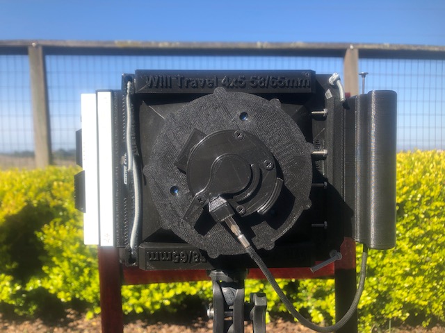 This uses a pinhole I made in brass sheet of about 0.3mm, so it has something around f.183 for exposure calculation.
The handgrip adds a little extra to the width, and is not critical for a camera that will mostly be used on a tripod, but it makes it easier to carry. It also helps keep the cable release out of the way. These pictures show the camera with a standard film holder in place.
The pinhole mount and shutter are not part of the Will Travel camera parts, though they also came from Thingiverse. In use I have a small elastic band running from the lever to a screw on the front face of the mount cap. This is just strong enough to keep the cover closed while allowing the cable release to open the shutter. Releasing the cable release causes the cover to snap closed. I found I had to make the shutter itself a little thinner because the camera view could just see the edge of it. I did this by setting a 1mm negative Z axis displacement in the slicer software and regenerating the gcode.
Pinhole shutter in action, MP4 version
Pinhole shutter in action, MOV version
Top View
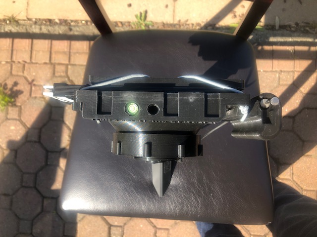 The top view shows the simple bubble level and the accessory slots. The front to back depth is short as there is no lens to project.
The cable release runs up the slot in the handgrip which keeps it out of the way. I made a small keyhole shaped block that threads over the cable
release and holds the plunger at the top of the grip. It is easy to slip out.
The top view shows the simple bubble level and the accessory slots. The front to back depth is short as there is no lens to project.
The cable release runs up the slot in the handgrip which keeps it out of the way. I made a small keyhole shaped block that threads over the cable
release and holds the plunger at the top of the grip. It is easy to slip out.
The circular recess on the top is one of the 3/8 inch tripod sockets. If the camera is set up for alternate handling (I like the film holder opening on the right as I hold it), this socket would probably get a 3/8 inch to 1/4 inch adapter installed. I used the one on the opposite side and added one to the handgrip for verticals.
Rear View
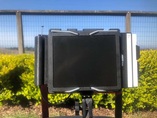 The rear view shows the bungee cord ‘spring’ back. There is no focusing screen on this camera, I just inserted a blank plate. With a pinhole there
is no need to focus and framing is best done by eye.
The rear view shows the bungee cord ‘spring’ back. There is no focusing screen on this camera, I just inserted a blank plate. With a pinhole there
is no need to focus and framing is best done by eye.
There are two versions of the focusing screen frame. This is the earlier one which uses a semi-fixed bungee routing. It works fine for slip in film holders or Cambo style slide in roll-film holders. Deeper roll-film holders would be better served with the alternate style which can be unhooked from the bungees.
In Use - Body with 90mm Super Angulon f/8
This lens is a respectable wide-angle on 4x5, works well with 6x12 roll film, and is a slightly wide normal for 6x9. It is a normal focal length for 6x7, and slightly long for 6x6. Although light, the camera is a bit bulky for the smaller roll-film formats. With a 6x9 Cambo roll-film holder which pokes out from the side, a finder on the top, and the big lens front element with a lens hood, the whole thing is quite impressive.
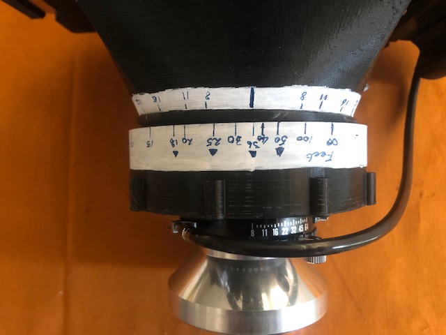
Focus Scale
Point and shoot cameras really require a focusing scale and depth of field guide to be useful. It helps to look up a depth of field table for the format you are using and determine the hyperfocal distances for the Circle of Confusion you choose. That gives some idea of the focus marks you will want. The idea is that if infinity is set to the upper aperture mark, then the closest focus should align with the lower aperture mark. For the f8 90mm, the aperture marks will be f8, f11, f16, and f22. By f32 the lens will start being diffraction limited, and exposures will demand a tripod, and at which point depth of field tables can be consulted.
Depending on the distances chosen it may be worth placing explicit hyperfocal distance marks as well as measured distances on the scales. This is a little quicker than setting the infinity mark to the upper aperture mark. A lot depends on how the scales align and personal preference.
- Put in an index mark down the centerline of the lens. Get this right, as everything else will reference this mark
- Find a suitable infinity test subject. It needs to be around a quarter of a mile or half a kilometer away and easy enough to focus on the screen.
- Use a dark cloth and a loupe for these settings - they need to be as good as you can make them.
- Mark the Infinity point
- Measure out a set of distances. Use the depth of field table as a guide to good points. Measure to the camera - typically to the shutter.
- At each point, mark the distance. If it is going to be a hyperfocal distance, put in the upper and lower aperture marks. This is a simple screw focus camera, so the marks for an aperture should be equally spaced either side of the index mark.
- Keep going until you get to around three and a half feet or one metre, or the focus ring comes all the way around.
Once you have your infinity point, you will probably want to reseat your lens to make the control placement optimum as the mount rotates. A long cable release is probably a good idea as you do not want to reattach it every time you focus close up.
 The 90mm f8 is a pain to focus accurately and repeatably compared to a 90mm f5.6. This is inevitable due to the comparatively small maximum aperture. I sanity
checked my marks by calculating the lens extension from the film plane and measuring with a digital caliper. It is also possible to calculate
the lens extension using the
Thin Lens Equation though how accurate this will be will depend
on your lens design. The 8mm pitch screw cap on this camera advances 8mm for one full rotation, so given the circumference of the cap it
is possible to create a scale to wrap around it. I also measured the lens extension from infinity using an f5.6 90mm lens
on my Wista 4x5 at measured distances. If you can narrow down the infinity focus point the calculated information will help with other distances.
Use a good loupe on the focus screen and be prepared to do some test exposures
at measured distances to confirm your scale. You should also do a sanity check of the mounted ground glass to make sure the depth matches the film holder,
otherwise the visual focus will be off.
The 90mm f8 is a pain to focus accurately and repeatably compared to a 90mm f5.6. This is inevitable due to the comparatively small maximum aperture. I sanity
checked my marks by calculating the lens extension from the film plane and measuring with a digital caliper. It is also possible to calculate
the lens extension using the
Thin Lens Equation though how accurate this will be will depend
on your lens design. The 8mm pitch screw cap on this camera advances 8mm for one full rotation, so given the circumference of the cap it
is possible to create a scale to wrap around it. I also measured the lens extension from infinity using an f5.6 90mm lens
on my Wista 4x5 at measured distances. If you can narrow down the infinity focus point the calculated information will help with other distances.
Use a good loupe on the focus screen and be prepared to do some test exposures
at measured distances to confirm your scale. You should also do a sanity check of the mounted ground glass to make sure the depth matches the film holder,
otherwise the visual focus will be off.
The triangular marks are hyperfocal distance indices for f8, f11, f16, and f22 for my chosen circle of confusion.
Front View
Apart from the obvious lens, this body is much the same as the shorter one. The bungee cord as been routed a little differently. There is no ‘right’ way, just use whatever works.
A Figure Eight Knot (Wikipedia) is a good choice for the end of the cord. It stops the cord from pulling through, but is slightly easier to undue than some alternatives. Since bungee cord stretches it can be come very tight with simple knots.
Top View
Very similar to the smaller body, but as this camera has to be focused there are index marks and scales added.
This focus screen is rough ground using 1000 grit carborundum paper. It is good enough for focus checks, but it is not really good enough for regular use. But this is a point and shoot camera, and that’s what the scales are for. If you never use the focus screen after setup, it could be replaced with a blank, as I did with the pinhole. However the screen is really useful for true framing of closeups.
Rear View
This camera has the alternative focusing back where the bungee cord is held under hooks. Deeper roll-film backs can be fitted by removing the focusing screen and using hooks (from the camera common components files) to reposition the bungees.
Will Travel References
See the Will Travel page.
Many of these designs are on Thingiverse.
Ideas
Strap Lugs
One way to fit a strap is to cut a length of webbing to fit under the handgrip (12mm / half inch or 19mm / three-quarter inch webbing) and sew D rings on each end. Punch holes for the grip bolts and either heat seal (nylon) or fray-check (fabric) the edges of the holes. Bolt the grip back on, sandwiching the webbing between the grip and the body. This will allow the camera to hang from a strap attached to the D rings, but not get in the way of normal use, though a cable release may need to be removed. It probably pays to add a focusing screen protector to avoid abrasion of the screen.
Screen Protector
Unless you keep a roll-film holder on the camera, the focus screen is a little vulnerable. This sort of camera is put in and pulled out of a bag a lot, so screen damage is possible. I made a square section asymetric ‘U’ shaped protector. Printing it on edge requires a minimum of a brim and good base adhesion, otherwise it may wobble towards the end of the print. The protector is inserted under the ground glass frame with the larger surface over the top.
Other Bits and Costs
The 1 Kg fof Hatchbox brand black PLA I used cost under $25 (2021) delivered. That did two bodies, grips, and some extra bits to build the two units, and left some over. Factoring in electricity, screws, the tripod adapters and bubble levels, and some cyanoacrylate glue, it cost about $35 for the pair. Granted, I already had a suitable 3D printer and some experience using it, and the 90mm f8 Super-Angulon came from my MPP VII kit (where it was under used).
For bungee/shock cord try Sgt. Knots on Amazon if you are in the US.
3/8” to 1/4” tripod screw inserts are available from various online sources, as are small circular bubble levels. Do check the bubble levels - some are not always consistent with a true level surface.
If you are interested in a ready-designed pinhole mount, see the Copal #0 pinhole shutter with shutter release cable mount by brettpim on Thingiverse. The threads for the Copal #0 mount are probably too fine to print on an FDM printer - I glued mine to the cap on the camera. I have a small elastic band that runs from the arm of the cover to the camera body. This provides just enough tension to close the cover when the cable release tension is let go, but without requiring much effort to open. Carry spare elastic bands!