These notes are based on the C3, C33 and C330 models. The principle is the same in all models, but the appearance of the controls does vary.
The lens assembly is retained in place by a stiff wire clamp. The wire is locked in place by a small metal cam on the lens board. This is brass on early models, black on later ones. This cam pivots out of the way of the wire when the bellows are fully closed and the control on the left body side set to ‘Unlock’. This cam is moved by a small plunger that projects from the camera body when the film change baffle is raised. Since this plunger does not project far, the bellows must be retracted. On the C3 and similar bodies, there is a chrome sliding knob (the ‘catch lock’) on the upper left side which must be slid towards the lens. Setting the control to ‘Unlock’ also raises the internal baffle that protects the film while the lens is removed. It is suggested that the lens is changed with the camera lying on its back. When mounting a new lens, take care that the body cocking lever (‘33’ and later series bodies) meshes with the shutter cocking lever on the lens. Lenses may be changed in the cocked or uncocked condition, but remember to set the replacement to the same state! It is inadvisable to change lenses on auto cocking bodies with the film part-wound, as this can mean that the shutter lever ends up on the wrong side of the cocking lever. Damage is very probable.
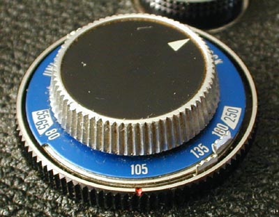
On the C33 and C330 models you should also change the focal length setting on the side dial so that the exposure compensation / parallax compensation indicator is correctly programmed. This image of a C330 side dial (c330/105onC330control.jpg) shows the lens lock control in the lock position, the film speed reminder at ISO 200, and the film type reminder as black and white. The inner of the two, ridged, sliders at the 5 o’clock position programs the focal length. It is currently at 180/250mm. Note that the 65mm and 55mm use the 80mm setting and the extra finder scale.
The large extension allowed by the bellows construction of these cameras permits magnifications of nearly life size with short focal lengths. At this degree of extension the effective aperture of the lens is reduced, and more exposure is required. The C33, C330, C330f, and C330s are all fitted with a mechanical guide which can be read in the viewfinder. The focal length in use is set using a dial on the left side of the body (see 5.1). As the bellows is extended a marker descends from the top of the frame. This is read against an engraved scale on the focusing screen which gives the factor for the extra exposure. The 55mm and 65mm lenses need further correction, as the closest setting on the camera is 80mm. This is usually achieved using a supplementary scale attached to the finder. See 6.4 Finders.
Tests suggest that the indicator should be read beneath the engraved factor, and not above or below.
The other cameras rely on a scale which is found on the left side of the bellows rack. This is marked in compensation factors for each focal length, and is read against an index mark on the camera body. Again, not all bodies have scales for all lenses. However exposure compensation for lens extension is calculable. Tests suggest that this scale can err on the conservative side by indicating up to +0.5 stops over the correct exposure. This exposure scale (jpg/cside2.jpg) from a Mamiyaflex (courtesy Ken Kirch) has two scales. One for the 80mm, and one for the 105mm and 135mm.
Table of Exposure Corrections, Magnification, Image width, and Parallax (J.Hein, personal communication)
| + F stop | Factor | Magnification | Viewfinder field | Negative field | Parallax |
| 0.25 | 1.19 | 1:11.05 | 56.3cm | 61.9cm | 0.5cm |
| 0.50 | 1.41 | 1:5.29 | 27.0cm | 29.6cm | 0.9cm |
| 0.75 | 1.68 | 1:3.37 | 17.2cm | 18.9cm | 1.5cm |
| 1.00 | 2.00 | 1:2.41 | 12.3cm | 13.5cm | 2.1cm |
| 1.25 | 2.38 | 1:1.84 | 9.4cm | 10.3cm | 2.7cm |
| 1.50 | 2.83 | 1:1.47 | 7.5cm | 8.2cm | 3.4cm |
| 1.75 | 3.36 | 1:1.20 | 6.1cm | 6.7cm | 4.2cm |
| 2.00 | 4.00 | 1:1.00 | 5.1cm | 5.6cm | 5.0cm |
First column: correction in f-stops
Second column: time correction factor (note the difference 1/2 stop and factor 1.5)
Third column: Magnification
Fourth column: Object field shown in view finder, starting from screen width of 51mm
Fifth column: Object field shown on negative, starting from negative width of 56mm
Sixth column: Shift of view image due to parallax
This table neglects the contribution of varying entry and exit pupil sizes. Users are advised to verify these figures with their own systems before using them for critical work.
A distinction must be drawn between parallax compensation, and parallax correction. The Mamiya lenses have the viewing and taking lenses displaced by 50mm. This means that they see slightly different views. In practice this means that the top of the frame of the viewing lens is also 50mm higher than the top of the taking frame. At distances over a metre or so, this has negligible effect. At closer distances, where the field of view may be as little as 65mm across, a 50mm discrepancy is over half a frame.
Parallax compensation demands that the image is framed, and then the alignment of the camera is adjusted by tilting the camera upwards. In the case of the cameras with viewfinder scales, the scale line determined by the exposure compensation should be aligned with that portion of the image which lay at the top of the screen during framing. With the C33 etc. this is the moving bar, on other models it is the line representing the 1.5x and 2x exposure compensation.
Because the taking lens was not on the same axis as the viewing lens, the spatial relationship of elements in a three dimensional subject will change. If precise control over this alignment within the subject is required, parallax correction is required.
The aim of parallax correction is simple. Move the camera until the taking lens is in the position occupied by the viewing lens without changing the angle of the camera. This can be done using a tripod with an adjustable centre column, though you are limited to keeping the camera back parallel to the column axis. Failing to do this means that the taking lens does not obtain the same angle and distance from the subject. Tripods with an angled column (such as the Benbo) will eliminate this problem.
The Paramender (See 6.1) provides the precise 50mm displacement required.
The most recent comprehensive lens tests available were done by Tim Brown, and can be found at the http://www.photo.net/bboard/q-and-a-fetch-msg.tcl?msg_id=0005l3&topic_id=35&topic=Medium%20Format%20Digest Mamiya TLR lens-tests