5x4 Cigar Box Pinhole Camera Project
I have used a Zero Image 6x9 pinhole camera for several years to good effect. Some photographs made with this camera have been popular even enlarged to 11x14”. Since I have 5x4 equipment, I have also used a pinhole in this format, but the minimum film to pinhole distance on the Wista is around 50mm, and that requires the camera bed to be dropped to keep it out of the field of view.
My wife acquired a selection of used wooden cigar boxes some years ago for an art project, and had several left over. These boxes are generally well made and finished. Better than the craft boxes you find at chain stores. I was able to find one just larger than the film holder with a pinhole to film distance of around 35mm when complete, and the game was afoot!
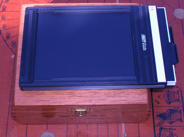
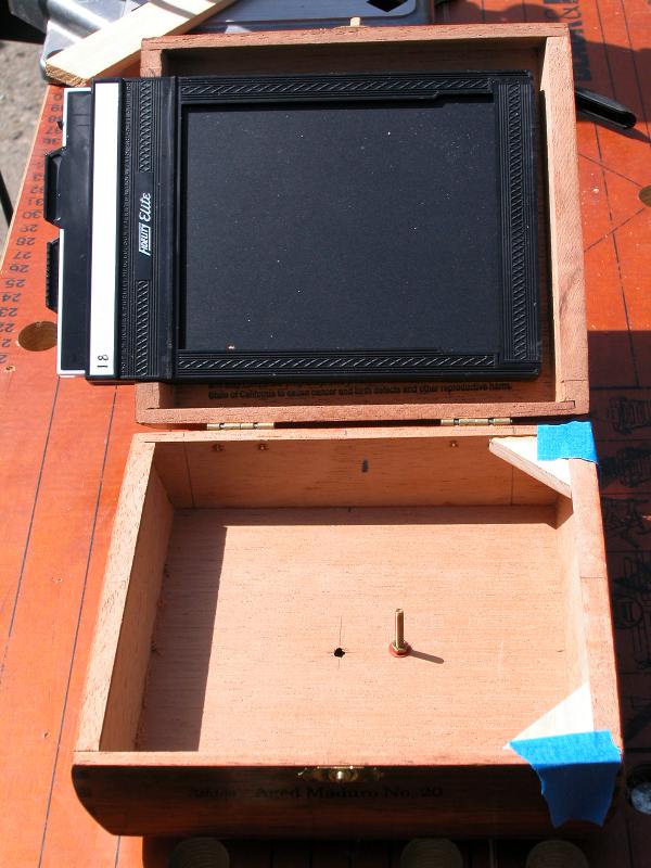
The box I chose had a lid depth that was just greater than the film holder. About 13mm internal depth compared to the 10mm of the holder. The lid dimensions also allow the holder’s retaining rib to fit inside which makes for a more secure installation. The aim with this design is that the lid acts as a locking back to hold the film holder in place while the darkslide is withdrawn for photography.
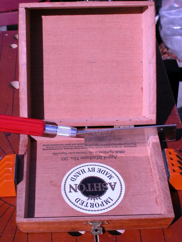
The film holder will be slightly offset, so the cross making the approximate center of the film (for the pinhole mount) is also off-centre. The various center marks were made by measuring the film holder and interpolating the centre point for the with and height. These lines were then projected to the base of the box using a set square, and into the centre. Pinholes are fairly forgiving about centering, but it is nice to get it close.
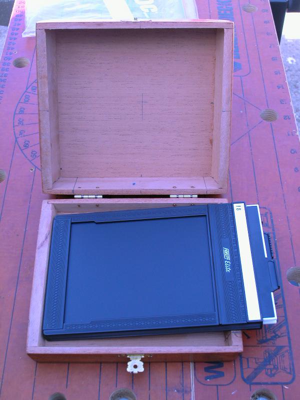
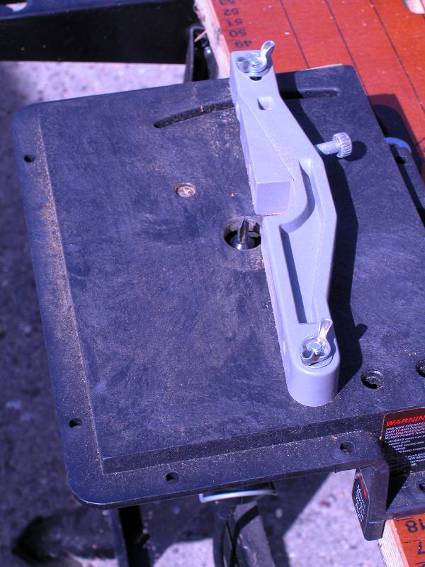
The first stage was to mark up the box with the section to be removed to accomodate the film holder. The intention is for the film holder to lie parallel to the lid rim so that it is held securely when the box is closed.
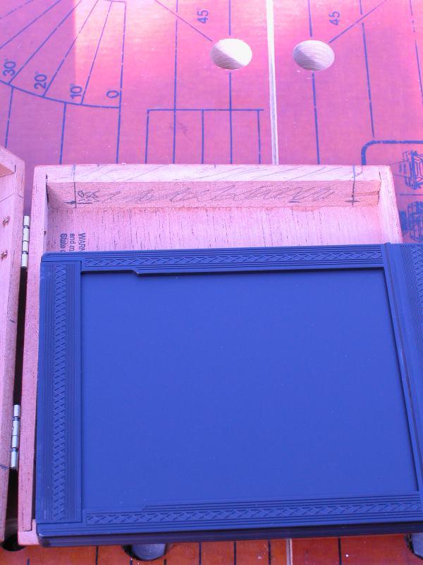
Making the end cuts for the film holder slot. I used an X-Acto razor saw, but any small, fine saw will do. The main thing is to get the gap right, and make the cuts square to the lid edge. A good fit makes it easier to plug any light leaks.
I used a router table for a hobby drill (Craftsman or Dremel) to remove the material between my saw cuts. A small table saw would do as well, otherwise you will have to make many cuts and remove the material with a fretsaw or chisel and sand smooth.
Starting to remove the wood to make the film holder slot. This is a coarse router bit to remove most of the material. I switched to a finer bit and made a final height adjustment to finish the cut. Frequent checks of the depth is a good idea.
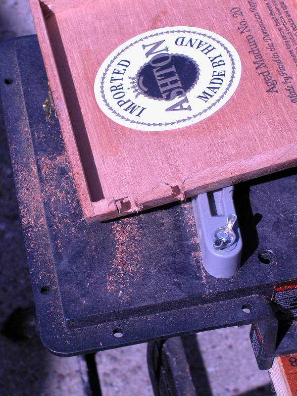
Finally, the holder fits the slot with the box closed.
A pilot hole is drilled for the pinhole. Then a large drill was used to make a shallow countersink on the outside of the box. This ensures that the pinhole is not vignetted by the thickness of the box base when it is mounted on the inside. The exposed wood in the countersink will be painted black to reduce glare.
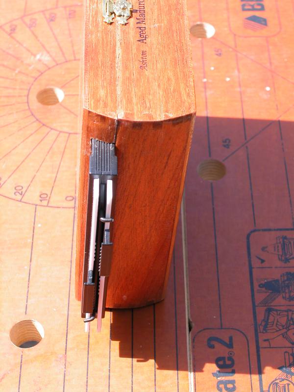
The shutter is a simple pivoted cover. This is a temporary cover to allow the main box to be tested for light leaks.
A pair of triangular gussets in the corner of the box will act as supports for the film holder. They are large enough to cross the holder corners without also crossing the film area. Here they are taped in place for a visual check with the film holder before being glued into the corners.
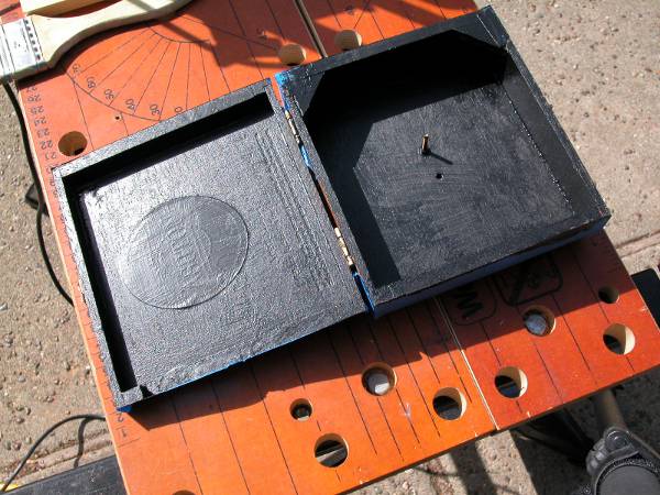
After the initial coat of black paint for the interior. To mask the edges of the base and lid, I ran wide masking tape around the closed box, and slit it along the lid join using a sharp knife. This gave a precise tape edge. The triangular file holder retainers are glued in place now. The bolt holding the ‘shutter’ has not been cut back yet. At the moment it would appear in the image. There is more painting to do - touching up, black paint on the outer pinhole surround, black paint on the inside face of the shutter, and varnish on the outside.
Basic light trapping with the film holder in place on the box section. The film holder is normally placed in the lid, and the lid closed, but this shows the light baffle requirements. The Velcro (loop side) is used for areas in contact with the film holder face. There is a strip under the film holder at the darkslide end which is not visible in this picture. Some sections of black computer mouse mat were used to baffle leaks from the lid/box edges and at the corners of the darkslide.

The shutter mechanism is a simple twist cover. This may be changed to a slider at some point. The main thing is to make sure the cover is not in the image because of the wide-angle nature of the design.

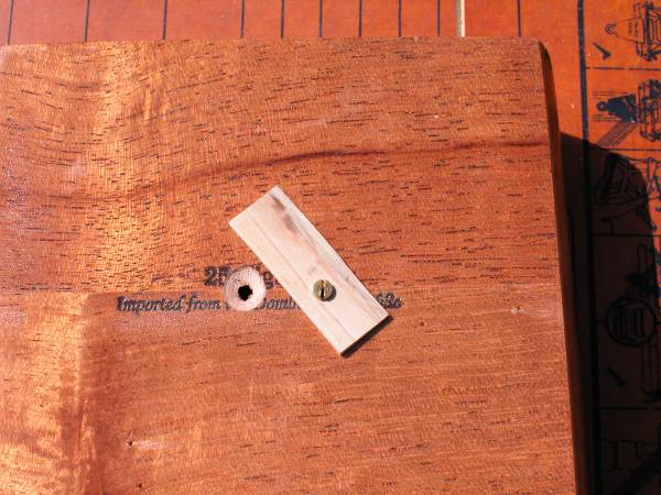
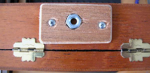
The tripod mount is essential in a camera where a fast exposure is around 1 second. I had two options. Use a 1/4” nut that matches a standard tripod screw and mount it in a block of wood using epoxy resin, or use a plate with the correct threaded hold from a canibalized quick-release mount. In this case I chose to use the nut in a block of plywood approach. The plywood block makes a platform that clears the hinges if I want to stand the camera on a flat surface.
The tripod socket is aligned with the pinhole, which means slightly offset in this example. The block also allows clearance for the lid to open fully which protects the hinges from damage and allows easy access for film holder changes and interior adjustments.
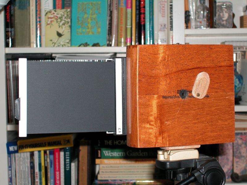
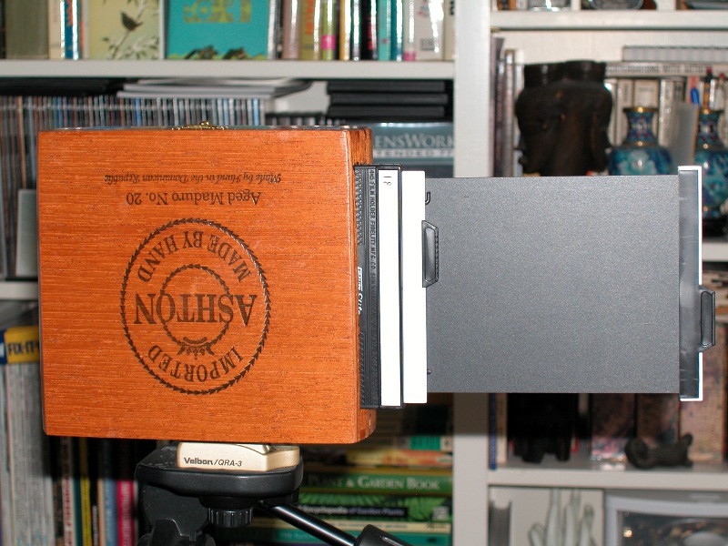
The finished camera from the front with the darkslide withdrawn most of the way. It is usual to pull the darkslide completely, but this gives a good idea of the dimensions.
The finished camera from the rear.
The pinhole itself is a self-manufactured one. I was aiming for something around f160 at 35mm, or about 0.22mm. This is bound to vignette in the corners due to effective light fall off. Probably around 3 stops if I can make the pinhole thin enough.
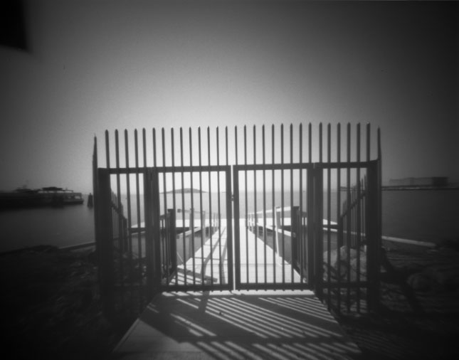
First test run. Delta 100 at EI 50, around six seconds, bright sun. Some pinhole vignetting can be seen.
April 2017 - I am going to try a laser cut pinhole from Daystar Laser Inc. On this camera a 300 micron pinhole should be around f180. The corner illumination should be better than my hand-made pinhole.